Stage 1: AutoCAD Drawing
Introduction
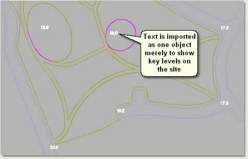
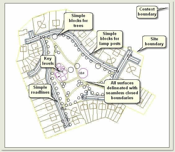
Before even starting to think about creating a 3D scene from AutoCAD data, a separate simplified drawing must be created taking elements from a design drawing. The drawing below is a good example of an AutoCAD landscape design drawing. However, this is not suitable for import into MAX/VIZ as it contains hatches, text, image references, detailed blocks etc that MAX/VIZ will not use

Just those drawing elements needed for creating good surfaces, edges and objects are copied and pasted into a new AutoCAD drawing and quickly optimised for export to MAX/VIZ
NOTE: Ref: 'Key Fundamentals / Infrastructure and Landscape Modelling' for guidance on how to use good drawing methods in AutoCAD
- In AutoCAD open Project for 3D 03.dwg. This is a much simplified drawing and is used in this tutorial. This exercise explains the steps used to create the drawing which is used as a 'buffer' drawing for importing into MAX/VIZ. This buffer drawing enables the drawing data to be optimised for use in MAX/VIZ/Key 3D and leaves the design production drawing unaltered
TIP: Keep elements in a design drawing on layers ready for easy copy and pasting to an optimised drawing for 3D to minimise any redrawing. A well organised CAD project should involve as little redrawing for 3D as possible
Download Sample Data
In order to follow this tutorial, you may want to use the supplied files. Please read the sample data instructions before downloading.
AutoCAD Drawing files: dwg_files.zip (784kb)
3ds Max Scene files: scene_files (7.8mb)
1.1 Setup a project folder
- Setup a project folder using the folders in the example below
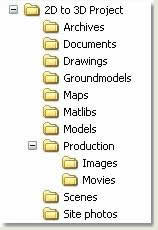
Unzip the training files to the relevant folders, putting the dwg files in the Drawings folder and the scene files in the Scenes folder
- In MAX/VIZ Customize > Configure Paths and configure paths for Import (Drawings folder) and Scenes (Scenes folder) on the General Tab
- Open Key 3D Templates
 and load Key 3D Template
NOTE: It is advisable to use the Key 3D Start Template as the MAX/VIZ Start Template. This contains many quick-start features and settings. Select the Key 3D Template and press MAX/VIZ Start Template to do this. It will then appear under the MAX/VIZ Start Template group box and will open up automatically when MAX/VIZ starts
- Save a scene to the Tutorial Files folder and name it: Key 3D tutorial 01.max. This scene file can be used throughout the tutorial and saved sequentially as Key 3D tutorial 02 / 03 / 04.max etc or pre-staged scenes can be loaded from the Scenes folder when prompted
1.2 Copy and paste from the design drawing
Whenever creating a scene from a design production drawing always separate the data to be used for 3D work by copying into a new drawing and naming this 'buffer' drawing specifically 'for 3D'. This helps deal with issues such as optimising framework lines, simplifying blocks and moving the data nearer to 0,0. It also removes most of the drawing data that will not be used by MAX/VIZ and allows for a straight forward and comprehensive transition. Below, is an explanation of how to do this, but for the purposes of this tutorial a buffer drawing has been created
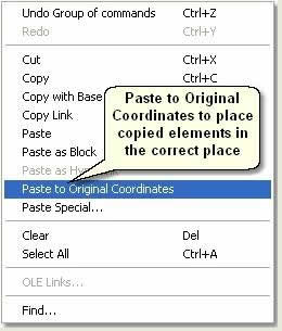
- Select elements from the design drawing and right click > Copy
- In a new drawing Edit > Paste to Original Coordinates. This will automatically paste the drawing elements in the correct place in world coordinates
- Name the new drawing 'xxxxx for 3D' to identify it as the buffer drawing to import the AutoCAD data into MAX/VIZ. The drawing used in this tutorial is called 'Project for 3D'
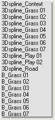
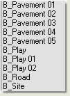
1.3 Layer management
- Open Project for 3D 03.dwg
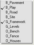
- Look at the layers. They have been named so that anybody (the acid test) can recognise any elements when importing to MAX/VIZ

TIP: Use a template drawing with predefined layers and blocks to speed up this process
NOTE: The 'G_Framework' layer is used to help create surface boundaries using the Boundary command
1.4 Optimise framework lines
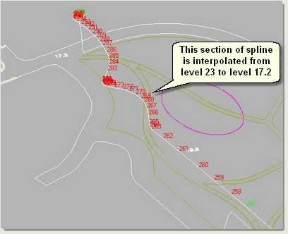
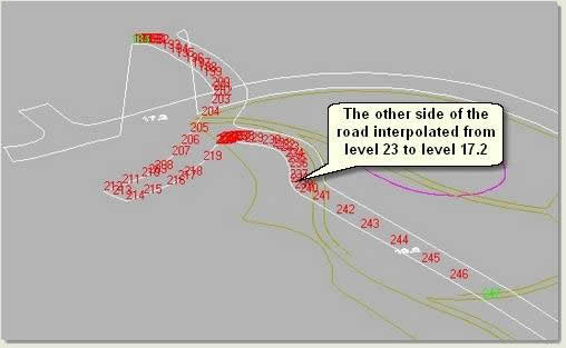
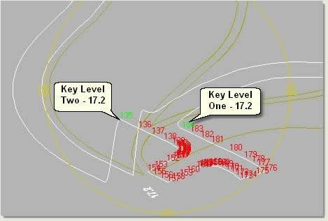
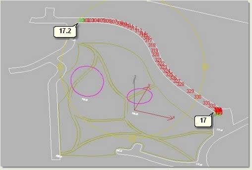
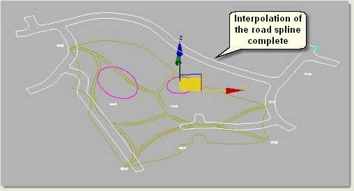
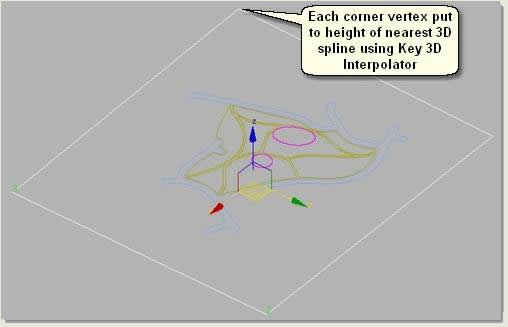
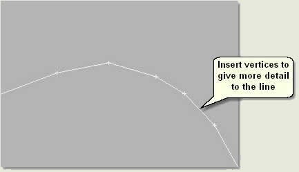
Optimising framework lines involves inserting, deleting or moving vertices to give the appropriate amount of vertices on the lines and improving design elements such as the smoothness of curves that would benefit the 3D graphics greatly. This optimisation will, in turn, optimise the boundary lines created from the framework lines in the next stage. To optimise the framework lines they are imported into MAX/VIZ and the powerfull spline sub-object tools used before exporting back to AutoCAD to create the surface boundaries
NOTE: A feel for the correct level of detail on the lines at this stage can overcome potential problems when creating a terrain from a copy of the lines at a later stage. Lack of faces or too many faces on parts of the terrain can be avoided
NOTE: This exercise outlines quite extensive editing of the framework lines to give you a wider experience of the MAX/VIZ sub-object editing tools. In practice, more would probably be done in AutoCAD to form curves around intersections and entrances before importing the lines into MAX/VIZ
- Open MAX/VIZ and make sure Key 3D Template is used (Ref 1.1). This contains many 'quick start' settings
- File > Import. Choose Files of Type: AutoCAD (*.DWG, .DXF) and select Project for 3D 01.dwg
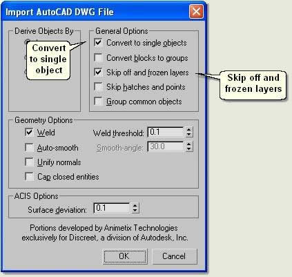
- On the AutoCAD DWG/DXF Import dialog > Layers Tab check Select from list and tick the G_Framework and B_Play layers
TIP: Uncheck these layers and press Invert to speed up the process of selecting the layers to import
- On the Geometry Tab uncheck all options apart from Weld at a threhold value of 0.1 This will make sure the lines will be imported as continuous lines and not a series of separate lines. Then press Ok to import the framework lines and play surface boundary lines
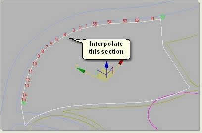
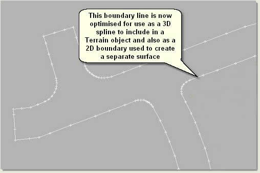
- Maximise the Top viewport and select Layer:G_Framework. This spline object needs optimising by inserting and moving vertices, mainly on the rounded sections to give smoother curves and more uniform geometry at path and road intersections and entrances. Also, on straight sections to give the lines more detail when used for terrain generation
Road framework line optimisation
Road corners
- Select Layer:G_Framework
- Enter vertex sub-object mode and zoom to one of the rounded corners at a road junction
- Use Refine on the Geometry rollout to insert vertices between existing vertices where needed with a view to creating a smoother and more uniform curve
- Select all the vertices on the curved section and change to Corner vertices

- Move vertices to create a smoother corner, without moving the end vertices on the corner
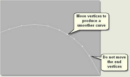
NOTE: In this instance vertices should be added. However, some imported lines may need vertices removing if there are too many. In general, use Corner type vertices whenever possible and adjust the level of detail to suit the proximity of final viewing
Road straight sections
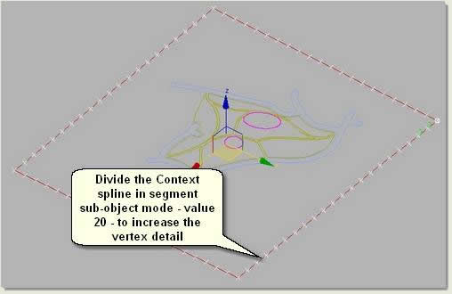
- On the straight sections add vertices at uniform intervals where there are pronounced lack of vertices. This will lead to a more uniform terrain at the end of the landform mesh creation process
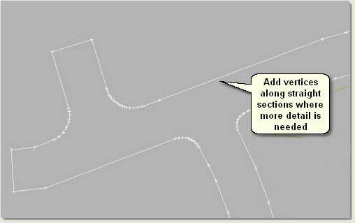
TIP: On longer sections where vertices need adding use the Divide tool in segment mode to quickly add uniform vertices
TIP: Be careful when selecting vertices and turning them to corner type. If you turn bezier type vertices to corner type on sections of the line that have not had vertices added then you will lose the intended geometry of the line (ie the line will not be 'anchored' with new vertices as intended). If this happens use Undo and re-select the line
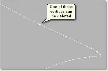
- Delete unnecessary vertices:
Path framework lines optimisation
The framework lines for the paths within the parkland have been created using arcs in AutoCAD. The vertices on these lines are translated into bezier type vertices when imported into MAX/VIZ and typically have few vertices on the lines. To optimise these lines and vertices for use in MAX/VIZ, the amount of vertices need increasing where needed, removing where not needed and the type changing to corner type vertices. Although the curves will then be made of straight segments (as with the road corners and due to using corner vertices), this method means that you have complete control over the level of detail required in the surface mesh. Plus, auto-generation of many faces as a result of using bezier type vertices on a boundary line when cutting out inner surfaces from larger surfaces later will be avoided
NOTE: Remember that the aim here is to get complete control over the amount of face detail on the final 3D surfaces. You need high detail around curves and within the more detailed design areas and less detail in areas of less detail design such as the middle of grassed areas and the context landform. The reason you are using MAX/VIZ to do this at this stage (before exporting back to AutoCAD) is because MAX/VIZ has more efficient tools to edit vertices on lines than AutoCAD
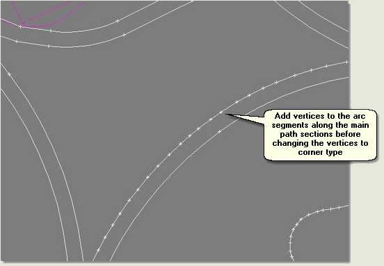
Main path framework lines
- Add vertices to the splines at regular intervals before turning the vertices to corner type vertices
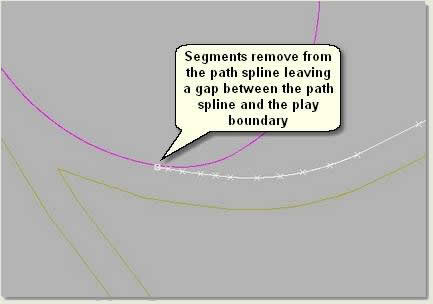
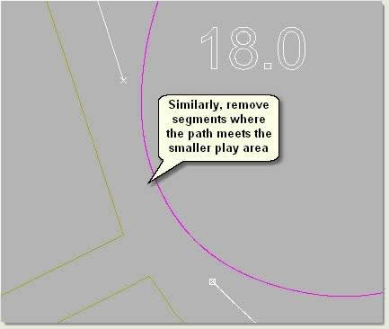
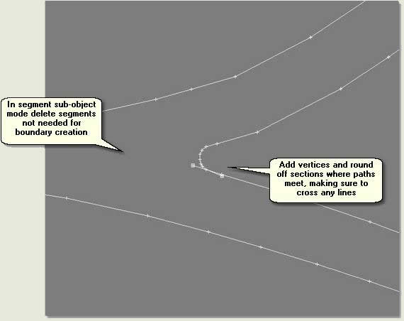
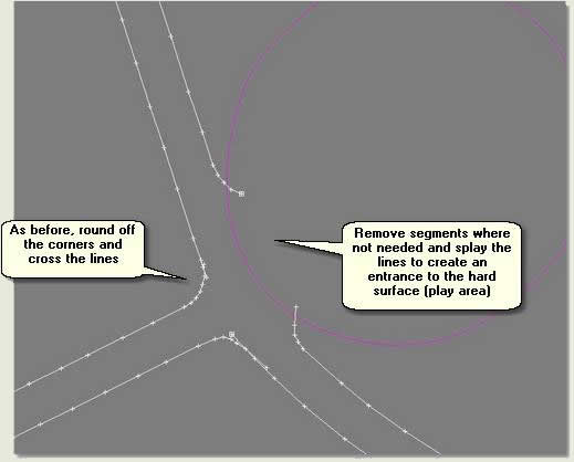
Intersections
- Where one path meets another delete any spline segments not needed for boundary creation
- Add vertices where needed and move vertices to round off the path lines, remembering to cross any lines. These will be used to create closed boundaries for the grassed areas in AutoCAD and should have no gaps
Entrances
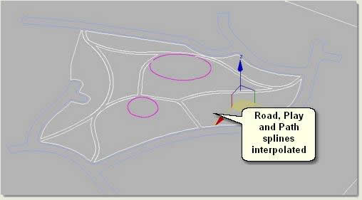
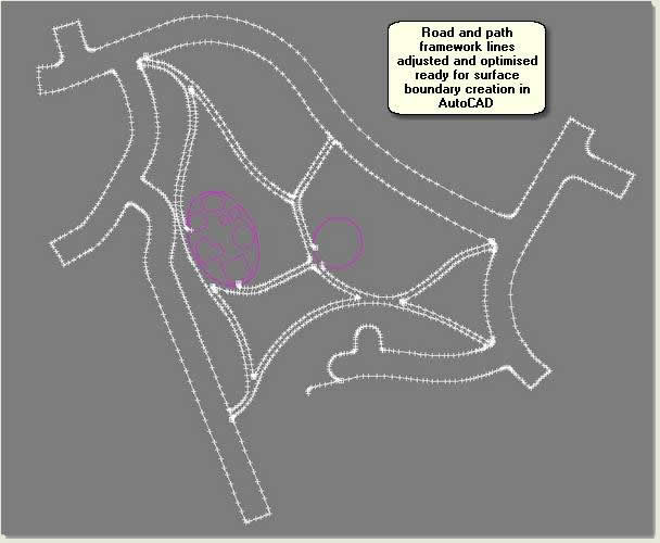
- Finally, and when confident the geometry on the framework lines has been optimised effectively, export the framework lines back to AutoCAD:
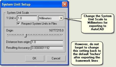
Firstly, change the System Unit Setup settings to millimeters:
- Customize > Units Setup > System Unit Setup button. Change the System Unit Scale to Millimeters. This will make the exported geometry the correct size when inserted into the project drawing
Then export the framework lines to AutoCAD:
- File > Export Selected. In the Save File to Export dialog choose Save as type: AutoCAD(*.DWG)
- Name the file Framework lines optimised.dwg and save in your training files folder
- Save the scene as Framework.max in case it is needed later
- When finished exporting change the System Unit Scale back to the default Inches
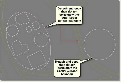
1.5 Create seamless closed boundaries for surfaces
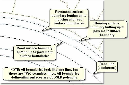
All boundaries for 3D surface creation must be drawn in AutoCAD as closed boundary polygons that have been created using accurate geometrical drawing techniques. This process has been aided by adding a framework layer that has been edited and optimised in MAX/VIZ. The Boundary command is now used in AutoCAD to create the surface boundaries and to make sure that all the boundaries are seamless
NOTE: Double lines delineating a kerb in the 2D plan are not imported into MAX/VIZ, just the seamless boundaries of one surface next to another. Kerbs are created entirely in MAX/VIZ by using the Key 3D Edging routines, involving the use of the Loft compound object. In MAX/VIZ the 3D kerb will extend over the 3D road surface which will be lowered about 150mm (as it is in real-world). Because the kerb will extend over the road it is the back of kerb line that is used for the road boundary
Insert the optimised framework lines drawing
- In AutoCAD open Project for 3D 02.dwg. The drawing exported from MAX/VIZ called Framework lines optimised.dwg has been inserted using the Insert command. For this exercise this drawing has most surface boundaries complete except the grassed areas. Note that the lines are now optimised
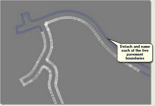
Create surface boundaries
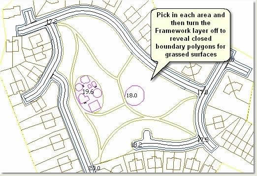
- Turn the Framework layer on and make the B_Grass layer current (B_ prefix means that this is a surface boundary)
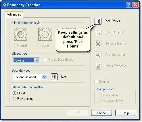
- Draw > Boundary. On the Boundary Creation dialog press the Pick Points button and pick in each grassed area to create a boundary on the current layer
- Save the drawing as Project for 3D 03 tutorial.dwg for your own use and do not overwrite Project for 3D 03.dwg
NOTE: A site boundary has been created on layer B_Site. This is used to create a site surface, thus separating the design surfaces from the context surface (which will be far less detailed)
NOTE: An advantage of creating surface boundaries using the Boundary command is that they do not contain 'intersecting vertices' (a common problem in 3D modelling work). Creating boundaries in this way also ensures that the polygons are completely closed. Closed boundaries are also useful in AutoCAD for hatching, obtaining area quantities and export to other 3rd party applications such as Corel Draw and Adobe Illustrator
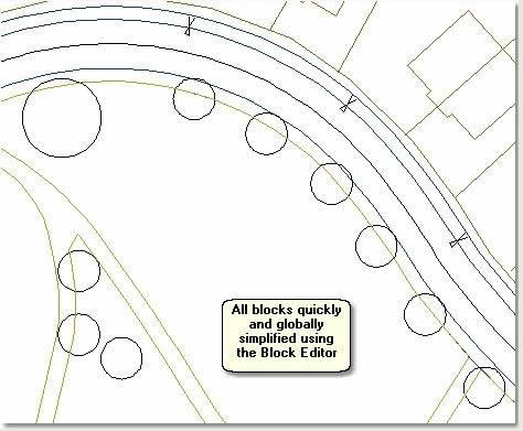
1.6 Replace detailed blocks with simple blocks for MAX/VIZ/Key 3D
Complicated 2D blocks should not be imported into MAX/VIZ if they are merely used as markers for 3D Objects or, as in this case, for replacing with 3D objects. Replacing blocks with much simpler blocks before importing into MAX/VIZ is straightforward in AutoCAD using the Block Editor. This exercise explains how this was done in the tutorial project drawings
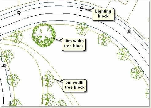
- In AutoCAD open Simplify Blocks.dwg. The drawing contains two complicated graphic blocks for trees and one lighting block. These have been used as part of the design production drawing, but the blocks are too detailed for import into MAX/VIZ
Redefine the tree blocks
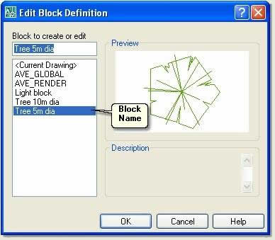
- Select one of the 5m tree blocks and double left click. This opens the Edit Block Definition dialog
NOTE: The Edit Block Definition dialog is a feature of AutoCAD 2007 plus. Replacing blocks in previous versions of AutoCAD entails using the Reference Edit dialog or simply 'redefining blocks'
- Press Ok to open the block up for editing in the Block Editor
- In the Block Editor make sure layer O_Tree 5m dia is current
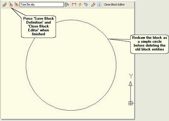
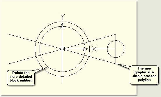
- Draw a circle from the centre of the existing block, making it the same diameter as the existing block
- Erase the existing block entities, leaving just the new simple circle
- Press Save Block Definition
 on the Block Editor toolbar and close the Block Editor dialog. All of the 5m tree blocks will be automatically redifined
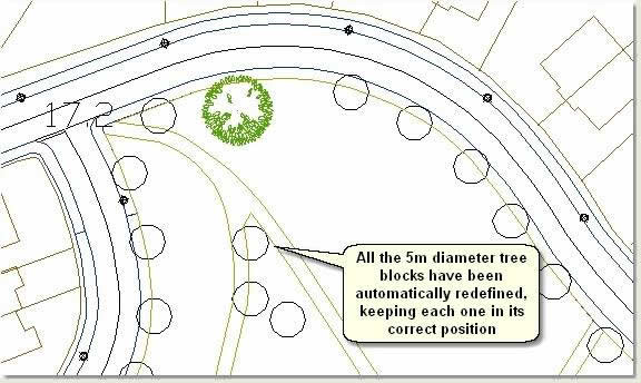
- Repeat this process to simplify the 10m tree blocks and the lighting columns, making sure that the correct layer is made current in the Block Editor. To simplify the lighting columns use the following graphic:
TIP: Another option for replacing blocks can be found on the Express Menu/Blocks. Use Replace block with another block to quickly replace a block in the drawining with another
1.7 Move data nearer to zero if required
The AutoCAD drawing used for this tutorial is positioned close to zero on the X and Y axes. However, it is very common for land planning and architectural project drawings to be positioned far from 0,0 due to the use of Ordnance Survey georeferenced data. This can cause problems later on in the 3D project, when some modelling operations may fail and animated cameras may 'shake'
- Refer to Key Fundamentals: Infrastructure and Landscape Modelling / Import Options / Move to Zero for detailed notes on how to move data close to zero in the buffer drawing without compromising the original production drawing